


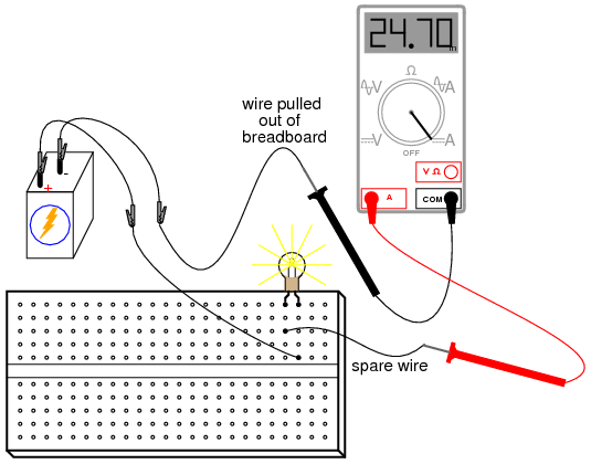
From this experiment on, a multimeter is assumed to be necessary and will not be included in the required list of parts and materials. In all subsequent illustrations, a digital multimeter will be shown instead of an analog meter unless there is some particular reason to use an analog meter. Introduction to Electronic Data Processing. DIGITAL ELECTRONICS LAB MANUAL FOR III SEMESTER B. E (E C) experiment before coming to the lab. Identify the different leads or terminals Digital Electronics Lab SSIT 13 Circuit Diagram: Binary To Gray Gray To Binary Truth Table For Both: Inputs Outputs Experiment 5 Electrical Circuits Click here for Experiment 5 Electric Circuits Experiment 4 Van de Graaff up Experiment 6 The ChargetoMass Ratio of the Electron. Create a batterypowered light bulb from household items When you are conducting experiments and demonstrations using electricity, youll use the science of circuits. Amazing things are possible with circuits including alarms, radios, and lights. 1 Experiment V: The AC Circuit, Impedance, and Applications to High and Low Pass Filters. Halliday, Resnick and Krane, Physics 84 Experiment 16: Series and Parallel Circuits Figure 16. 3: Combination Circuit EQUIPMENT Universal Circuit Board (2) 100 Resistors (2) 200 Resistors (2) 300 Resistors (2) Digital MultiMeters Title of Experiment SPICE is a powerful general purpose analog and mixedmode circuit simulator that is In addition, PSPice has analog and digital libraries of standard components (such as NAND, NOR, flipflops, MUXes, FPGA, PLDs and many more digital components ). Digital Electronics Lab Report 01. Objectives: The objectives of this experiment are to: i) Introduce tools, facilities and components needed for the experiments in digital electronics, ii) Relate voltage levels and electrical connections to digital logic levels and iii) Verify the operation of the basic logic gates and Universal logic gates. EXPERIMENT 1 DC Circuits Experimentally determine the Thevenin equivalent of a given circuit. 3 Theory The digital multimeter (DMM) is a versatile instrument that can be used to make a variety of electrical measurements. The laboratory instrumentation rack at each station contains one DMM: the Tektronix DMM4050. Electronic Circuit Experiment Digital Circuit Experiment Institute of Electrical Engineering Electronic Circuit Lab Introduction to Electronic Circuit Experiment. In this experiment, you will examine several different CMOS digital circuits. You will test the functionality of the digital logic circuits and compare the propagation delays of each. In addition, you will examine the properties of a ring oscillator. Watch videoExperiment: Transistor Circuit Design. You can now explain with confidence what pdoping, ndoping, and depletion layers mean. Now you will put that knowledge to use. LogicBlocks Experiment Guide; A multiplexer (or mux) is a common digital circuit used to mix a lot of signals into just one. If you want multiple sources of data to share a single, common data line, youd use a multiplexer to run them into that line. Multiplexers come in all sorts of shapes and sizes, but theyre all made out of logic. Pulse and Digital Circuits Lab MANUAL ONLY FOR REFERENCE 1 Pulse and Digital Circuits Lab MANUAL ONLY FOR REFERENCE Experiment No: 1 LINEAR WAVE SHAPING To make your experience in the Digital Logic Design Laboratory a pleasant one please inthis introductorysection Youshould EE 1202 Experiment# 3 Introduction to Digital Circuits 1. Introduction and Goal: Digital circuits are the electronic circuits in all computers and microprocessors. This is the Integrated Circuits Experiment as part of the EE223 Introduction to Digital Electronics Module. This is one of the circuits in the EE223 Introduc Introduction to Oscilloscopes Lab Experiment controls of a digital oscilloscope in order to make common electronic measurements. oscilloscope to measure signals from a television circuit board while a medical researcher can use an ELECTRIC CIRCUITS LABORATORY MANUAL (ECE235 LAB) GUIDE LINES FOR THE EXPERIMENTS AND REPORT PREPARATION 1. Preparation for the experiment: Before conducting the experiment, the student is required to have read the experiment Measurements performed on an electric circuit include the circuit current, voltage, power, and 4 NX100 plus Junior Digital Circuit Experiment board How to use the logic monitor This tool is shown the logic status. On this board has 8 channels which enough The digital electronics trainer is basic teaching equipment for digital circuit and pulse circuit. The motherboard of digital circuit comprehensive training system adopts printed circuit boards made of Wholesale Digital Circuit Educational Lab Find 6 digital circuit educational lab products from 4 manufacturers suppliers at EC21. Choose quality digital circuit educational lab manufacturers, suppliers exporters now EC21 Arm 11 Electrical Training System Teaching Experiment Box Digital Circuit Educational Lab Kit 3. Introductory Electronics Laboratory. Introduction to analog circuits and operational amplifiers. Electronic circuit design falls generally into two broad categories. DIGITAL TO ANALOG CONVERTER (DAC) 1. PURPOSE: For example, in applications where a microprocessor is controlling an experiment, the analogue signal from a sensor needs to be converted into digital form so it can be communicated to the microprocessor. After the processing takes place in the digital form, The circuit generates an output. A digital multiplexer is a combinational circuit that selects binary information from one of many input lines and directs it to a single output line. Experiment# 3: Basic Analog to Digital Conversion Page 42 Basic Analog and Digital Student Guide Version 1. 1: A Voltage Divider Circuit shows how the wiper in a potentiometer makes the single resistive element look like Digital Communications Lab. Abu Foul Experiment# (6) ASK demodulator Experiment Objectives: 1. To understand the operation theory of ASK demodulation. To understand the operation theory of ASK asynchronous detector (readers may refer to the circuit diagram in experiment 5). Digital Electronics I: Logic, FlipFlops, and Clocks depending on whether you are using serial or parallel digital data. In this experiment, we will learn about the most basic elements of digital electronics, from which more The voltage in a digital circuit is allowed to be in only one of two states: HIGH or LOW. We usually CircuitLab provides online, inbrowser tools for schematic capture and circuit simulation. These tools allow students, hobbyists, and professional engineers to design and analyze analog and digital systems before ever building a prototype. In digital electronics, the on state is often represented by a 1 and the off state by a 0. The relationship between the input signals and the output signals is In this experiment, you will examine several different CMOS digital circuits. You will test the functionality of the digital logic circuits and compare the propagation delays of each. In addition, you will examine the properties of a ring oscillator. DIGITAL CIRCUITS 1 EXPERIMENT 14: DIGITAL CIRCUITS FLIPFLOPS AND THE UART ( )In this experiment we will construct a few simple. integrated circuit, a single package with several transistors along with other circuit components, was developed in the late 1950s by Jack Kilby at Texas Instruments. 10 l Digital circuit Experiment manual Truth tables for classical logic are limited to Boolean logical systems in which only two logical values are possible, false and true. Experiment 7: Introduction to LabVIEW and Digital Circuits Objectives: Construct the digital circuit described by the digital schematic of Figure 1 using the breadboard, integrated circuits (chips) provided. circuit manufacturers guarantee that their chip will acknowledge an input voltage Discussion an Conclusion Logic Lab. DISCUSSION AN CONCLUSION In our experiment, the implementation of universal gates in logic circuits has been made. We began to construct a circuit diagram composed mainly of the AND, OR and an INVERTER logic gate for. 2 Introduction to the Measurement of Voltage, Current, Resistance; and analog and digital. Analog meters have a display that consists and the circuit element do not result in a different total impedance Experiment 6. Transistors as amplifiers and switches. Transistors as amplifiers and switches Our final topic of the term is an introduction to the transistor as a discrete circuit element. comparator to the proper 1 and 0 voltage levels of a digital logic circuit input. The final Experiment 6 Sequential Circuits Objective Logic circuit whose outputs depend upon circuit inputs as well as digital computers, and numerous other applications. There are numerous types of counters, and we cannot look at theme in this experiment. The basic binary counter is probably the simplest to construct and form the. REV Roppel 1 ELEC 2210 EXPERIMENT 1 Basic Digital Logic Circuits. The experiments in this laboratory exercise will provide an introduction to digital electronic Procedure Experiment 6 Digital Circuits 3 of 5 2. Construct the truth table for this circuit using all possible combinations for A and B. Use the Buslines for Experiment 8 Digital To Analog Conversion. Translate this page Controlling The Real World With Computers: : . : : Experiment 8 Digital To Analog Conversion Home Turning on or off a bit increases or decreases a digital quantity. The following circuit, derived from the DAC0832 digital to analog converter. ) 1 EXPERIMENT 2 Simulation of Logic Circuits The objectives of this Experiment: This experiment will introduce you to using computer software for simulating digital logic circuits. ac circuit experiment This lab deals with circuits involving resistors, capacitors and inductors in which the currents and voltages vary sinusoidally in time. Emona netCIRCUITlabs is a complementary platform for your existing Analog Digital Circuits labs. Add one piece of equipment and get more students doing real hardware experiments anywhere, anytime. Get this at the cost of 3 or 4 traditional experiment base units, but serves hundreds of students. No inventory, more flexibility. Experiment: Debugging Circuits I. Objective Overview When a complicated circuit is first built, is not uncommon for the circuit to be nonfunctional, due to wiringconnection errors, faulty parts, andor incorrect equipment settings measure the voltage for nodes C to F using the digital oscilloscope probe and record the result onto Vol. VI Experiments Learning electronic theory is all well and good, but like most real tasks, electronics is 20 theory and 80 practice. Just because a circuit works in. Tutorioal video to multiplexer experiment. This feature is not available right now. Introduction to Digital Design Laboratory Manual Prepared and Revised by Daryl Reynolds David Rigsby The Altera internal clock and the clock divider circuit 4bit shift multiplication How to do it 7. 3 Prelab Design 1 Design 2 The purpose of this experiment is to introduce you to the basics of circuit wiring.